Simple Single phase AC motor starter using PLC

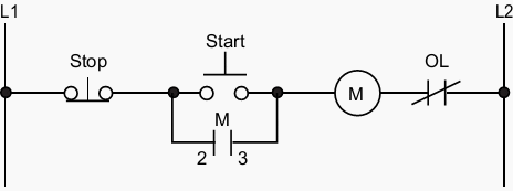
Simple Induction Motor Starter Circuit

PLC Ladder Program for the Above Circuit
with addition of overload flashing indication
It will select the CPU then press O.K Now press Communication tab.
You will get following window , now double click the to refresh the communication.
it will communicate with plc and set the comm port.
Star- Delta connection arrangement
PLC used Siemens S7-200
PC software used Step 7-Microwin V4.0.5.08

Electrical Connection Diagrams of PLC
This PLC has 14 input in two groups (I0.0 to I0.7 and I1.0 to I1.5) outputs in two groups.
Q0.0 to Q0.7 and ( Q1.0, Q1.2) see the I/ O diagram below.
This Cpu is operated by 24 Volts DC.
All its inputs are source inputs (You have to connect +ve of the supply to the inputs)
DC supply connections are M (-ve) and L+ (+ve) can be seen upper right corner.
This Cpu is operated by 24 Volts DC.
All its inputs are source inputs (You have to connect +ve of the supply to the inputs)
DC supply connections are M (-ve) and L+ (+ve) can be seen upper right corner.
Induction Motor
Cut view of induction Motor
Motor terminal block Connections
Winding connections arrangement
Pictorial view of Motor terminal block
Simple Induction Motor Starter Circuit

PLC Ladder Program for the Above Circuit
with addition of overload flashing indication
In the above ladder program Network 1 is the one which is doing the main job, as switch on and switch off the motor.In this program input are shown with "I" and output with "Q" this is Siemens notation system different manufacturer have different notation system as Mitsubishi co mention with "X" for input and "Y" for output.
How to make your first Program
When first you start the Step-7 Micro/Win program you will see the following window.Double click on CPU-
224 or what ever CPU is there on the left side as shown in the image below.
Another window will pop-up, as shown below. click Read PLC tab to select the CPU type.
You will get following window , now double click the to refresh the communication.
it will communicate with plc and set the comm port.
Now PLC is ready to make and test the program
Traditional Star-Delta circuit of Motor
Star Delta Starter Theory
Electrical motors have been used in industries for quite a long period of time to convert electrical energy into mechanical energy. Three phase induction motors, also called asynchronous motors, are most extensively used motors in industries because of certain advantages like self starting, robust design, simple construction, less maintenance, efficient and comparatively low cost, though there is a problem of peak starting current associated with these motors. Peak starting current can be up to 5 to 7 times of full load current (flc) and sometimes it may become as high as 10 times of full load current. However, the problem of peak starting current remains only for few seconds till the motor attains its speed, this problem may become severe especially with the motors above 10 HP. To deal with the problem of peak starting current or inrush current associated with three phase induction motors, many different starters having different mechanism and principle of operation are used. Star-delta starters are used for motors ranges from 5 hp or 3.5 kW. Star delta starters first configure windings of 3 phase motors in star thereby reduce voltage across each winding and then after few seconds these starters configure windings in delta and motors start run at full load voltage without any difficulty.


No comments:
Post a Comment